These multi-analog channel data acquisition methods, learn well, you are a master
With the rapid increase in sensors and signal sources in electronic systems, device designers can add more analog signal channels to the system MCU or sensor fusion coprocessor. This is especially true in the growing field of small Internet of Things.
Signal averaging is a technique commonly used in such data acquisition systems to enhance the available resolution of numerical results and suppress multiple noises. Although the filtering method is simple, the overall effect depends on the averaging method used. This article compares the traditional sequence averaging method with the latest cross-average method.
Many modern mixed-signal MCUs and system-on-a-chip directly incorporate averaging into analog-to-digital converter hardware. This greatly reduces the amount of processing that the MCU needs to accomplish, simplifies code writing, and reduces the runtime required by the processor in high power modes.
Although analog input multiplexers that connect multiple signals to devices are common, the hardware averaging function of most mixed-signal MCUs can only be performed in one signal channel at a time. When the averaging process is completed, an interrupt is usually triggered and the firmware selects another analog input that needs to be converted in the interrupt. In some devices, such as Cypress Semiconductor's PSoC 4 Series 1 Msps 12-bit ADC programmable system-on-chip, its channel sequence is built into the converter hardware to perform averaging on all channels without processor intervention. Features.
This traditional average model for multiple conversions of a single channel signal to the next channel is called sequence averaging. There are some limitations to this approach, the main problem being that it reduces the available sample rate in a multi-channel environment, including the channels that are averaged and the channels that do not need to be averaged in the sequence.
A new approach has recently emerged that can enhance the tools used by data acquisition system designers. Known as the cross-averaging method, this technology brings the gospel to systems that need to acquire high-frequency signals and need to quickly acquire non-average channel samples.
The difference between sequence averaging and cross averaging can be explained from some images. This article selects an 8-channel configuration as an example. The raw ADC sample rate is set to 800 ksps and the 16 12-bit samples in each channel will be averaged together. This produces a 16-bit output word, and the 12-bit sample quantized SNR contribution limits the signal-to-noise ratio to the level of the 14-bit converter (assuming that the quantization noise contribution per sample is not correlated) .
Since there are 8 channels and each channel is sampled 16 times to obtain the final result, ACD needs to perform 128 conversions to generate each result group. This process takes 160 microseconds and the resulting set of frequencies is 6250 beats per second.
This example also assumes that each channel has its own result register, as is the case with PSoC 4 used in this example. However, some mixed-signal MCUs differ, they only have one result register, so they have to be read while the channel is being converted.
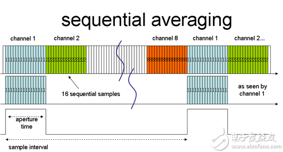
Figure 1 shows the standard sequence averaging solution in pseudocode form, which behaves as follows:
Refresh accumulation register
Select channel 1
16 samples at 1.25 microsecond intervals, accumulating them in the register of channel 1, which takes 20 microseconds
Select channel 2
16 samples at 1.25 microsecond intervals, accumulating them in the registers of channel 2, which takes a total of 20 microseconds
Repeat the above steps to complete sampling of 8 channels
Transfer 8 results, interrupt or DMA

Figure 1: Sequence average
Sequence average
Channel 1
16 sequence samples
From channel 1
Aperture time
sampling interval
Each input is sampled by 16 consecutive conversions. The continuous conversion of one channel takes 160 microseconds, so the sampling frequency of each channel is 6250 samples per second. The sampling aperture (ie, the sampling time of one channel) is 20 microseconds. This aperture produces a low-pass filtering effect, however the bandwidth is very high, with a zero point of (1/20 microsecond) 50 kHz multiple frequency response. This filtering does not prevent aliasing. Any frequency component in this input signal that is a multiple of 6250 Hz will be aliased down to a level close to DC, potentially making significant measurement noise. This can only be mitigated by pre-filtering each channel's anti-aliasing filter.
In addition, a time offset of 20 microseconds occurs between channels. If you need to calculate cross-channel math functions (such as correlation or power calculations), this time offset can cause serious errors.
If there are unaveraged channels in such a sequence, the sampling frequency of such channels is primarily determined by the channels that need to be averaged in other sequence samples. Therefore, although the sampling frequency of the ADC is 800 ksps, the sampling frequency of the unaveraged channel is much lower than this. The ideal situation is to evenly spread the 800 ksps frequency to 8 channels, each with a frequency of 100 ksps.
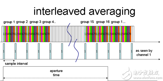
The solution to this problem is much more effective than the cross-average rule (see Figure 2). The sequencer surrounds the input channel as before, but this time only one sample is acquired for each channel. After the channel has been sampled N times, the output of all accumulation registers can be read.

Figure 2: Cross Average
Cross average
Group 1
sampling interval
From channel 1
Aperture time
The cross-average sequence in pseudocode form is as follows:
Set the hardware loop counter to 0
Refresh accumulation register
repeat
Cycle counter += 1
Select channel [loop counter]
Take a sample and accumulate it in the register of the channel [loop counter] for a total time of 1.25 microseconds
Until the loop counter ≥8
Transfer 8 results, interrupt or DMA
The signal characteristics of this averaging process are significantly different. There is no continuous conversion now, and 16 conversions for each average are evenly distributed. Each conversion takes 160 microseconds and is separated by 10 microseconds. In other words, the sampling frequency per channel is 100 ksps, which is the theoretical maximum when the 800 ksps ADC is spread across 8 channels. The sampling aperture for this process is 160 microseconds, so the system frequency response zero will appear at multiples of the final used frequency. This has the advantage that high frequency noise with aliasing reduced to DC does not occur in the input signal. This greatly increases the stability of the measurement, which significantly reduces the analog filtering requirements.
There is still a time offset between the channels, but it has been reduced to 1.25 microseconds, which is much smaller than the 160 microsecond sampling time, greatly reducing the error in cross-channel calculations.
In this example, the converter subsystem using the cross-averaging method provides 8 channels of samples at a frequency equivalent to about 14 bits of signal-to-noise ratio and 6.25 ksps, and effectively prevents aliasing and shortens the delay time between channels.
The cross-average method is being implemented on Cypress Semiconductor's new programmable chip system devices, including the recently introduced Cortex M4-based PSoC 6 and Cypress's PSo4 family of analog products PSoC Analog Coprocessor. The hardware in the device's ADC (which can be fully configured with the PSoC Creator Scan_ADC component) can also convert any channel in the sequence without performing averaging. This means that in the earlier example, the channel can still reach 100 ksps without affecting the average channel time.
The acquisition of multiple channel samples at high resolution and high sampling frequency greatly increases the possibility of economical and high performance analog signal capture using modern mixed-signal programmable system-on-chip. When you need to convert multiple analog channels that may require averaging, be aware of the effects of multiple averaging modes on the signal processing capabilities of the device.
The Smart Screen Protector Cutting Machine can help stores reduce the inventory of Screen Protectors. It is mainly used to cut Screen Protectors such as Mobile Phone Screen Protectors, Watch Screen Protectors, Tablet Screen Protectors, Pad Screen Protectors, and personalized fashion Back Films. It is very suitable for personal business or shop drainage.
Universal Screen Protector Cutting Machine has 20000+ cloud data of different specifications and models, adopts massive cloud database, and all data is updated synchronously in the state of networking. You'll have a full range of screen protector models on one machine and cut any Screen Protector model as needed without having to stock up on Screen Protectors for various phone models. No more losing customers due to missing models.
Screen Protector Cutting Machine,Protective Film Cutting Machine,Back Sticker Cutting Machine,Phone Sticker Cutting Machine, Film Cutting Machine
Shenzhen Jianjiantong Technology Co., Ltd. , https://www.mct-sz.com
