Unknown oscilloscope 12 martial arts
An oscilloscope is an indispensable tool for designing, manufacturing, or repairing electronic devices. In today's fast-paced world, engineers need to use the best tools available today to quickly and accurately solve the measurement problems they encounter. In the eyes of engineers, oscilloscopes are the key to successfully addressing today's measurement challenges. Modern digital oscilloscopes have time-saving features such as deep storage and a range of analysis tools that simplify the challenges of high-speed digital design.
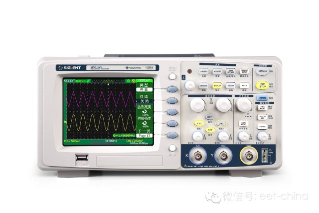
The following are a breakdown of the oscilloscope or 12 features that were previously unknown. 1. Protocol Decoding Serial bus manual decoding based on the oscilloscope waveform display is time consuming and error prone. In this relatively simple I2C signal, there may be problems. Can you easily find this problem? Can even tell what the signal represents? To manually decode the packet, you need to find the header, data bits, and trailer. All data signal states (blue) are checked against the clock state (**) and converted to a hexadecimal value.
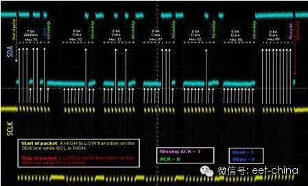
Figure 1: I2C signal on an oscilloscope
Manual decoding is compared here with the automatic decoding example. Simply define which channels the clock and data are on and define thresholds for determining the logical values ​​("1" and "0") to let the oscilloscope know the protocol being transmitted over the bus. At a moment, the serial data can be decoded and displayed to indicate the start bit, address bit, data bit, and end bit in the bus waveform display. For the I2C bus, the address and data values ​​can be displayed in hexadecimal or in binary.
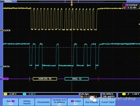
Figure 2: Automatic I2C decoding
2. What should I do if the network analyzer needs to measure return loss (Sdd11) or insertion loss (Sdd21) but no TDR or VNA? You can use high-bandwidth oscilloscopes to make some measurements that approximate network analysis, although this seems to be somewhat out of scope and certainly has some limitations. Traditional frequency response time testing involves the measurement of fast pulses and the viewing of the response FFT. In addition to this measurement, you can measure return loss and insertion loss with some fairly basic settings. For example, some high-speed standards (like PCI Express 3.0 and USB 3.0) include measurements with a long string of logic values ​​of "1" followed by a long string of "0"s. This constitutes a steady state condition or a low frequency state. The test pattern is then changed to a clock or 1010 pattern, also known as a Nyquist diagram. A comparison of the front and rear voltage levels yields a nominal insertion loss value. More advanced techniques and custom signal excitation can be used to extract additional details. A good work on the technical overview of a program can be found in a white paper entitled "Ethernet Differential Return Loss Measurement on Digital Storage Oscilloscopes" (?cs=wpp&ci=2748).
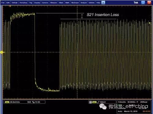
Figure 3: 64 "1" and 64 "0" followed by "1010" graphics
3. Playing a movie on a DVD drive What can I use as a large LCD screen? To be sure, you can watch the Signal Integrity Analysis Guide on your oscilloscope, but even more enjoyable is that you can watch the most recent movies (but you can't watch 3D videos yet). 4. Filtering Do you need to measure low frequency signals with high bandwidth oscilloscopes but don't want high frequency noise? Many oscilloscopes have digital signal processing that can be filtered, including low-pass filtering. Next time, when you want to measure a 100MHz clock on your 12GHz oscilloscope, you can use the bandwidth limit function for better signal-to-noise ratio and more accurate measurements. 5. Broadband Radar Test Digital oscilloscopes already have FFT capabilities. As radars and other broadband RF systems enter the digital arena, oscilloscopes now have transient or wideband bandwidth RF signal analysis capabilities. You can perform pulse analysis, digital demodulation, and EVM measurements on wideband radar, high data rate satellite links, or frequency hopping communication systems without external downconverters.
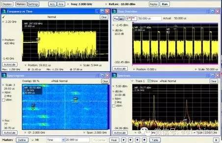
Figure 4: Oscilloscope showing wideband radar signals 6. Improving vertical resolution Most oscilloscopes have an A/D resolution of 8 bits. With different acquisition modes, the vertical resolution can be increased by averaging adjacent samples as described below. So how much can the resolution be improved by averaging and using high resolution mode? In theory, the increase is 0.5Log2N, where N is the average of adjacent samples. The reality is that a 2-byte memory depth limits this increase. The two bytes are 16 bits. One of the bits is reserved as a sign bit and the remaining 15 bits are used as data values. The rounding error causes the 14th and 15th bits to become random values, thereby making the actual limit become 13 bits. Therefore, the improvement can start from about six significant digits and can be increased to about 13 digits with a height oversampling.

Figure 5: Improve vertical resolution
7. Oscilloscope-based signal generator
Because many oscilloscopes have computer I/O ports, such as USB ports or Ethernet ports, these ports can be used to generate test signals. Simply download the appropriate software (found on the website of many standards bodies) to activate the test mode and you have a signal generator.
8. Test file
If you want to analyze on an oscilloscope like most people, you may need to have some test files. Learn about the test reporting features in many integrated software analysis tools to save you some time. To be more efficient, you can automate the analysis and test report operations by remotely controlling instrumentation instructions. Even basic oscilloscopes have time-saving features for files, such as the “Save All†feature, which allows you to save screenshots, waveform data, and setup files with the push of a button.
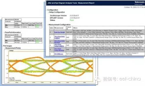
Figure 6: Use of the file test report feature
9. Intelligent retrieval
Finding events of interest in long waveform records can be time consuming without the right search tools. Today, with record lengths of more than 1 million data points, locating your events may mean browsing thousands of signal activity screens. Use a software search tool to simplify browsing of long records. There is even a front panel controller that allows you to zoom and pan quickly, just like watching a video with a DVR. By the way, it is also possible to automatically mark the occurrence of each defined event so that it can move quickly between events.
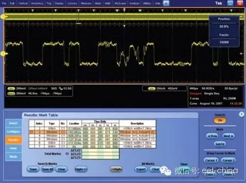
Figure 7: Use of tags in long data records
10. Trigger
The oscilloscope's trigger function performs simultaneous horizontal scanning at the correct point in the signal and is indispensable for clear signal verification. The trigger controller allows you to stabilize the repetitive waveform and capture the one-shot waveform. In high-speed debugging applications, your circuit may work 99.999% or longer. And it is .001% of the time that will cause your system to crash or just a part of the waveform you need to analyze in more detail. Advanced triggering features such as AB dual event triggering, window triggering, logic authentication, etc. all help isolate problems faster than searching millions of data samples after acquisition.
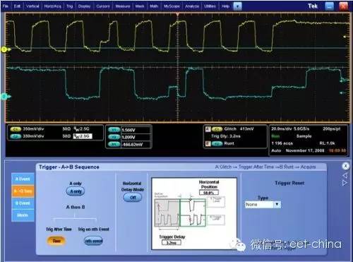
Figure 8: Advanced trigger mode reduces search for long data records
11. Remote control of the instrument
Have you ever had the experience of forgetting to check measurements or save test results before leaving the lab? Can't I access the oscilloscope remotely without special software tools? Fortunately, simply open the browser and enter the oscilloscope's IP address to easily access the oscilloscope. Many oscilloscopes, even basic oscilloscopes, can be networked not only in the lab, but also as web servers that can be accessed online.
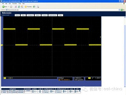
Figure 9: Network Driven Oscilloscopes can be accessed remotely via a browser
12. Eye diagram
What is an eye diagram? Through eye diagrams, people working in the field of high-speed digital design can recognize patterns in which multiple bits are superimposed on each other and are widely used. How can I quickly verify millions of bits without having to look at it? In a transient diagram, you can get an idea of ​​the effects of time variations, noise, ringing, and other signal integrity that can cause unreliable system operation. Most oscilloscope users are familiar with this tool, but many people are not aware of advances in signal processing and visualization techniques to deepen their understanding of this basic graphic. Through the eye diagram, you can basically understand the parameter values ​​such as voltage level and edge rate. If you extend this concept further, you can use BER contours to infer or predict the bit error rate. The figure below is similar to the eye diagram, but it shows the bit error rate as a function of timing jitter and voltage noise.
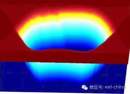
Figure 10: Eye diagrams and more information can be seen on the oscilloscope.
Conclusion The oscilloscope is easy to learn and easy to operate, helping you work efficiently and increase productivity, allowing you to focus on design rather than measurement tools. Just as there are no car drivers in the world that can be used as standards, there are no standard oscilloscope users in the world. Whether you use an oscilloscope for extensive analysis, for filtering, or for creating test files, the most important thing is how to operate your oscilloscope flexibly.
wedge prism (also known as wedge angle prism) is an optical prism with an inclined plane, which is mainly used in the optical field for beam control offset. The inclination of both sides of the wedge angle prism is relatively small. It can make the optical path deflect to the thicker side. If only one wedge prism is used, it can offset the incident optical path at a certain angle. When the two wedge prisms are combined, they can be used as a deformation prism It is mainly used to correct the laser beam. In the field of optics, wedge prism is an ideal optical path adjusting device. Two rotatable prisms can adjust the direction of the outgoing beam in a certain range (10 °).
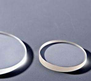
Wedge Prism
Hanzhong Hengpu Photoelectric Technology Co.,Ltd , https://www.hplenses.com
