ABB inverter fault code analysis method and main circuit analysis method
ABB inverters are widely used, and various faults are inevitable during use. There are two methods for generally handling ABB inverter faults (other inverter fault handling is similar): fault code analysis and main circuit analysis.
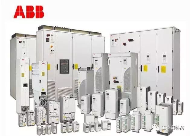
If the ABB inverter has a fault, there is a corresponding fault code on the operation panel. When dealing with the inverter fault, you must find its fault code on the operation panel and perform deep analysis according to the fault code. In the following, based on the experience of the individual in the repair process of the inverter and some common fault codes, some common troubleshooting methods are discussed.
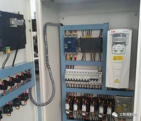
1.1
Fault code: BRAKE FLT
Cause: The brake is faulty, the brake is open, or the brake is not open.
Treatment method: Open the cover of the brake on site, forcibly open the brake coil in the program, observe the brake limit open state, if the brake can not be opened or the mechanism is stuck, replace the brake;
If the limit is open, the distance from the limit sensor is far, adjust the distance of the sensor and ensure its fastening. According to the author's years of equipment management experience, the failure rate of the electronic proximity switch is much lower than that of the mechanical switch. The limit is improved from the mechanical switch before installation to the electronic proximity switch);
If the brake is timed out, two methods can be used: 1 when the brake is opened slightly, the brake opening delay time is lengthened; 2 the brake is opened very slowly, and the new brake hydraulic push rod must be replaced.
1.2
Fault code: MF COMM ERR
Cause: The master and slave bus communication is invalid.
Solution: Check the fiber connection between the master and slave bus connections and the master CH: to the slave CH:. See if the connection is tight. If it is loose, reinsert it and make sure the connection is reliable. In addition, it is necessary to check whether the fiber communication is normal and whether the fiber head is clean. If it is not required, it must be cleaned with a precision electronic instrument cleaning agent or replaced with a good quality fiber.
If the above conditions are normal or the fault cannot be eliminated, the inverter contactor output coil is forced to operate for about 5 minutes in the program, and the fault can be eliminated.
1.3
Fault code: SHORT CIRCUIT
Cause of the fault: The externally connected motor cable is faulty or the inverter itself is faulty.
Disposal method: Disconnect the output line of the inverter, measure the relative insulation of the three grounds and the three-phase power unit with a megger. If there is a problem with the motor or cable, replace the motor and cable; if the output is normal, check the main inverter. The circuit mainly checks IGBT, inverter block and rectifier bridge. How to judge whether the IGBT, inverter block and rectifier bridge are normal? Here I will test the above-mentioned intact electrical components with a multimeter diode file. The test results are as follows:
1 For IGBT, the multimeter black meter test C, the red meter test E, the resistance is about 0.34MΩ, and vice versa. The other four cases are all infinite.
2 For the inverter block, the black meter of the multimeter is used to measure the positive pole, and when the red meter is used to measure the negative pole, the resistance is about 0.67 MΩ, and vice versa. The multimeter black meter measures the grounding pole. When the red meter is used to measure the negative pole, the resistance is about 0.34MΩ, and vice versa. The multimeter black meter measures the positive pole, and the red meter measures the grounding pole. The resistance is about 0.34MΩ, and vice versa.
3 For the rectifier bridge, the multimeter black meter is measured 1, and the red meter is measured at 3, the resistance is about 0.37MΩ, and vice versa. The other four cases are all infinite.
If the test result deviates too much from the above results, it is recommended to replace it. If you consider reducing the impact of maintenance on production time, I suggest that it is preferable to replace the inverter directly, because replacing one inverter
The device takes time to control, about 2h, and because of the SHORT CIR-CUlT fault code, the time is much longer than 2h, and the time is uncontrollable.
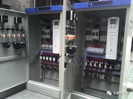
1.4
Fault code: AMBINET TEMP
The cause of the malfunction: The operating temperature of the inverter is too low.
Treatment method: The electric room air conditioner considers adding air conditioner to improve the working environment temperature of the inverter; if the emergency wants to resume the fast operation, the heating temperature can be increased by using a heating tool such as a hair dryer.
2, the main circuit analysis methodThe main circuit analysis method starts from the main circuit of the inverter and analyzes the cause and solution of the fault. According to experience, when you encounter the main circuit failure of ABB inverter, you can start from the following aspects.
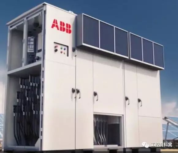
2.1
Fault caused by filter capacitor
The cause of the fault: the grid voltage is unstable, and the internal temperature is too high, and the component performance is not good.
Solution:
1 Mainly because the equipment is unstable and susceptible to electromagnetic interference;
2 Replace high quality components and improve ventilation.
2.2
Inverter over temperature
The cause of the fault: the fan does not turn and the air duct is blocked.
Solution:
1 Check the fan coil for damage;
2 Clean up the dust on the cold air duct. If the oil is stuck, add light oil and add some solid grease.
3 When replacing a new cold air fan, pay attention to some fans with automatic rotation signal, and some without fan rotation signal, replace the original fan.
2.3
Output current is too large
Fault cause: The output current exceeds the set limit and trips.
Solution:
1 Check if the motor load is short-circuited;
2 Check that the motor brake is fully open;
3 Check if the mechanical rotating device is flexible;
4 Judging whether there is temperature rise, odor, abnormal noise, etc. during the operation of the asynchronous motor;
5 After determining the motor and winding coil failure, pay attention to the original model and parameters when replacing.
2.4
Brake failure
Fault reason: The brake is not in operation, the in-position signal limit does not work, and the brake is mechanically faulty.
Solution:
1 Check if the brake supply is normal;
2 Check if the brake mechanical transmission is normal;
3 Check the brake coil failure;
4 Check the brake limit and return signal;
5 Check if the contactor is normal;
6 The main fault of the contactor is caused by poor contact of one contact or looseness of the contact terminal screw. Repair and replacement of new components should be taken. The brake should be damaged and replaced. Please pay attention to the original model and parameters when replacing.
2.5
Encoder failure
Fault cause: The inverter detects an error in the data signal returned by the encoder or is interrupted with communication.
Solution:
1 Check that the encoder is properly connected to the motor or device;
2 Check that the encoder signal cable is intact;
3 Check the connection between the encoder and the control board;
4 Check if the encoder is disturbed by surrounding equipment;
5 Correct the encoder position to eliminate other interference.
2.6
Interference fault
The cause of the fault: mainly conductive interference and electromagnetic induction interference.
Solution:
1 Mainly check whether the grounding wires are good;
2 Check that each shielded cable is connected properly.
The above are typical faults and treatments that have occurred during the use of ABB inverters in recent years. In order to effectively reduce the failure rate of the inverter, it is essential for daily inspection and maintenance.
Regularly remove dust, check whether the bolts are loose, check whether the cooling fan is running normally, check whether the cable and signal wires are loose, overheated, deformed, check whether the cooling silicone on the rectifier module and the inverter module is dry, check the wiring of the control system and Whether or not each electronic component is abnormal is the main starting point for inspection and maintenance.
Non-Contact Detector,Non Contact Voltage Tester,Voltage Tester Pen,Non Contact Voltage Detector
YINTE TOOLS (NINGBO) CO., LTD , https://www.yinte-tools.com
