Software Design of Camera System Based on STM32
System software design
About the STM32 on-chip resources, the basic configuration of the LCD ILI9341 LCD screen, the SD card driver and file system, the introduction of the OV7725 camera function has been described in detail in the previous chapter. The hardware platform is built on the STM32 development board and other device modules. This chapter mainly uses top-down, layer-by-layer detailed programming ideas, and modules explain the software implementation process of the whole system.
3.1 top-level programmingThe basic flow of the STM32 camera can be described as: system initialization, photo processing. First, system initialization, the system comprises a clock configured for buttons and GPIO interrupt enable, LED's GPIO initialization; reinitialization of the LCD GPIO, registers and internal bus function on FSMC; FATFS also initialize the SD card file system and enable the SDIO interrupt; and finally, after the analog bus SCCB, OV7725 also need to configure the GPIO FIFO OV7725 and internal registers, initializing field and a signal line. Then, the photo processing: waiting for the frame synchronization signal, enter the camera; wait for the button, start taking the picture (ie, the LCD screen capture) and save the picture to the SD card, as shown in Figure 3.1 .
3.2 system initialization program design3.2.1 GPIO initialization
The input and output modes of the registers and pins of the GPIO have been introduced in the main control module of Chapter 2, and the implementation of the multiplexing function has also been described in detail. Under control of the LED STM32, KEY, and the GPIO LCD, SD card, all GPIO pins or special function is provided using the camera must be implemented (FIG. 3.2) by a flowchart.
3.2.2 LCD initialization
LCD initialization mainly includes two contents: FSMC bus configuration, LCD register configuration, see Figure 3.3 . The program's read and write operations involving the LCD screen (such as clearing the screen, setting the liquid crystal scanning direction and writing picture information) are all implemented by writing commands and data to the two areas of Bank1_LCD_C and Bank1_LCD_D . Among them, the meaning of the command / data can refer to the contents of the ILI9341 reference manual, and the meaning of some instructions is also given in the liquid crystal display module of Chapter 2.
3.2.3 SD card file system initialization
The SD card file system initialization can be divided into two parts: SD card interrupt initialization and hardware initialization. How to set the function interface of the interrupt and FatFs file system has been introduced before, Figure 3.4 is the initialization flow chart of the entire SD card file system.
3.2.4 OV7725 initialization
The initialization of the camera OV7725 is divided into three parts: GPIO initialization of the SCCB bus and FIFO, initialization of the sensor, and initialization of the field signal line. The SCCB bus timing has been mentioned in the previous chapter. Figure 3.5 is the program flow chart of the OV7725 initialization.
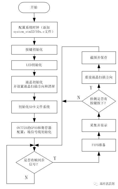
Figure 3.1 Main program flow chart
           Â
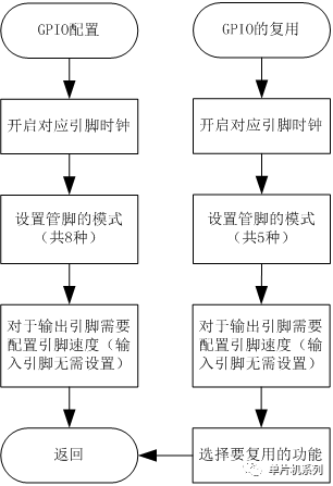
Figure 3.2 GPIO configuration and reuse
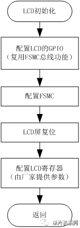
Figure 3.3 LCD initialization process
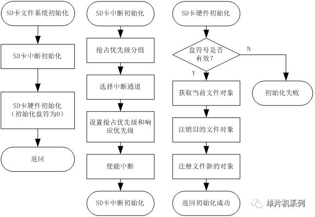
Figure 3.4 SD card file initialization process
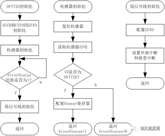
Figure 3.5 OV7725 initialization process
3.3 Photo Processing Program DesignThe first few sections detail the implementation of the initialization of each sub-module. From the main block diagram, there are also FIFO preparation, image acquisition and display, interrupt service routine, LCD screen capture and save subroutine. FIFO preparation (enable data out FIFO output), image acquisition and display is through the process of repeatedly reading the output of the FIFO and writing data to the LCD register, which can refer to the FIFO in the liquid crystal display module and image acquisition module in Chapter 2. Timing. The final section focuses on the process control of LCD screen capture and image preservation, as shown in Figure 3.6 .
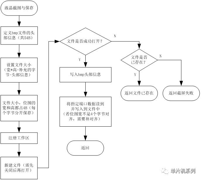
Figure 3.6 LCD screen capture and save process
Unshielded Smd Inductor,Inductor Wire Wound Inductor ,Split Core Ct Transformers,Split Current Sense Transformer
Shaanxi Magason-tech Electronics Co.,Ltd , https://www.magason-tech.com
