Speaker sensitivity: What is 1 watt?
The sensitivity of the speakers may be one of the most common misunderstandings among the various common indicators. The amplitude-frequency response of a speaker has often been reduced to a single value, which is sensitivity. This is the root cause of misunderstanding. Some people think that this value represents the loudness of a certain speaker when playing back a certain signal; others will think that two speakers with the same sensitivity will have the same loudness when playing back the same signal.
Both views have limitations. In fact, the sensitivity of the speaker is only for the specific bandwidth and spectrum content signal, in order to reflect the sound pressure level of the speaker. That is to say, if the two speakers with the same sensitivity index have different frequency responses, the output sound pressure level may be different when the same signal is reproduced. One of the decisive factors here is bandwidth. Let's take a look at the impact of bandwidth in this and explain why sensitivity sometimes does not require 1 watt as a reference. According to IEC60268-5, the sensitivity measurement of the speaker is a pink noise signal with a limited bandwidth. The RMS voltage is equal to the square root of the rated impedance of the speaker, and the sound pressure level is determined by reference to the distance of 1 meter.
The pink noise bandwidth limit is determined by the effective frequency range of the speaker to be tested. The purpose of this is to ensure that the test signal is within the effective output frequency range of the device under test. Assuming that a speaker cannot replay a signal below 150 Hz, it is of no use even if it is given a low frequency signal below 150 Hz, which only causes the voice coil to heat up. By the same token, if the speaker cannot reproduce a signal above a certain frequency, it is not necessary to give it a higher frequency test signal. When we measure the transfer function of the speaker to be tested at a higher resolution and express the average amplitude-frequency response of the speaker to be tested in a logarithmic frequency coordinate system, the sensitivity image of the speaker is obtained.

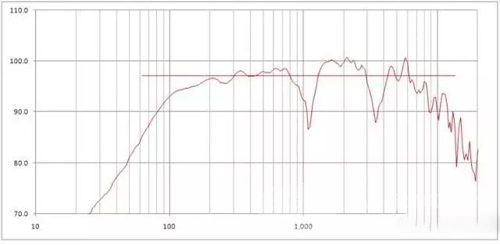
Take Figure 1 as an example. This is the response of the positive axis of a speaker. The line in the figure represents the sensitivity of the speaker. The length of this line is consistent with the upper and lower limits of the pink noise used to measure sensitivity. Figure 2 shows the spectral composition of the noise signal. If the wideband level of the signal is kept constant, but the spectral composition of the signal is changed, can the same sound pressure level (ie sensitivity) be obtained when the speaker is driven? To understand the answer to this question, we must know the spectral composition of the signal and the response of the speaker. (Note that 20Hz-20kHz here, and 110Hz-8.3kHz in Figure 1, does not mean the response of the speaker. We still need to get the actual response curve of the speaker.) If you don't know this, we can't infer the problem. answer.
Figure 1 A speaker's amplitude frequency response and single value sensitivity index

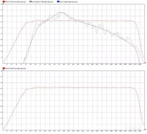
Figure 2 Signal channel used to measure the sensitivity of the A speaker in Figure 1. Figure 3 shows the spectral composition of the three different signals.
One of them is a pink noise signal with a defined bandwidth for measuring the sensitivity of the speaker. The other two are linguistic signals, and the other is a noise signal synthesized in the form of a linguistic spectrum. The reason why the noise signal of the imitation language is used to replace the real language signal is because the RMS level value of the imitation language signal is more stable, so it is easier to measure the output sound pressure level of the speaker to be tested. The wideband RMS levels of these three signals are substantially equal. The level of the imitation speech signal is higher than the pink noise in the 200-800 Hz band; in other frequency bands, the pink noise level is higher than the imitation speech signal.
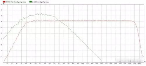
Figure 3 The red curve is the signal spectrum used to measure the sensitivity of the A speaker in Figure 1. The gray is the spectrum of the speech signal. The blue is the spectrum of the simulated speech noise signal similar to the spectrum of the actual speech signal. This figure is compared with the speaker response of Figure 1. Than we can see that the output of the speaker below 150Hz is very limited. The highest output of the speaker response is located in the 300-3kHz section. If you use this imitation language signal to drive the speakers, then it is reasonable to say that the sound pressure level is higher than that of the speaker with the same level of pink noise. This is the case. The sensitivity of this speaker is 97.1dB. However, when driven with an imitation speech signal, the sound pressure level is 98.1 dB, which is 1.0 dB higher. This is because the frequency band with a higher level of the imitation language signal is also the frequency band with a higher sound pressure level of the speaker output. Conversely, if you use the low-frequency noise of Figure 4 to drive the speakers, you can imagine that the resulting sound pressure level will be lower than the ordinary pink noise.

Because the main energy of the noise in Figure 4 is concentrated in the lower frequency range of the speaker output. The measured sound pressure level of the low frequency noise is 94.9dB, which is reduced by 2.2dB.
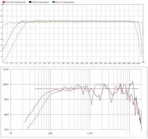
Figure 4 The red curve is the signal used to measure the sensitivity of the A speaker in Figure 1. The green curve is the pink noise that limits the bandwidth at the low frequency. Next, let's compare two different speakers. Figure 5 is a comparison of the A and B speakers. The sensitivity of these two speakers is the same, both 97.1dB. However, the low frequency and high frequency extension of the B speaker is better than that of the A speaker. Therefore, the pink noise used to determine the sensitivity of the B speaker has a larger bandwidth than the A speaker (Figure 6). Therefore, the level of the intermediate frequency of the noise of the B speaker will be slightly smaller than that of the A speaker. This observation is a bit difficult, but a closer look reveals that the black curve is about 0.5 dB lower than the red curve on the 100-10 kHz portion. This is because the signal bandwidth used by the B-speaker (black curve) is larger.
Be aware that the broadband levels of these two signals are the same. So, what if you use the broadband pink noise signal (20Hz-20kHz) in Figure 6 to drive the two speakers at the same time? Since the two example speakers here are not very responsive in the IF section, there may be some differences in sound pressure levels. However, readers don't have to worry about these issues for the time being. In other cases, the sound pressure level of the speaker with a larger effective frequency range (high and low frequency extension) should be larger. When using broadband pink noise drive, the output sound pressure level of the B speaker should be slightly larger. In fact, the measured B speakers are 0.8dB larger than the A speakers, one of which is 97.0dB and the other is 96.2dB.
As can be seen from these examples, the magnitude of the sound pressure level produced by the speaker depends on the transfer function of the speaker and the spectrum of the playback signal. Some indoor sound field simulation software will incorporate the above into the simulation range when calculating the sound pressure level of a certain audience. They allow users to choose pink noise, a language spectrum, or a user-defined spectrum. This helps the sound system designer to better predict the sound pressure level performance of the sound system during playback of a particular program material during the early design phase.

Figure 5 Amplitude response and single value sensitivity of A (red) and B (black) Figure 6 Spectrum of sensitivity signals for measuring A (red) and B (black), and broadband noise spectrum (green)
Another point is that at the beginning of this article, I mentioned that it is not necessary to use 1 watt as the reference value of the speaker to be tested. The reason why I feel that the current audio system should not use this method is as follows. First of all, how much voltage is needed for a certain speaker to be tested to make the driving power exactly 1 watt, which is more troublesome to judge. We can measure this value using a two-channel FFT measurement system, as well as a current monitoring device or probe. The question is how much useful information can this provide for designing, calibrating a speaker or sound system?
We can simplify this measurement and no longer tangled with the actual 1 watt of power consumed by the speaker under test. For example, we can use the pure resistance equal to the rated impedance of the device under test to generate the voltage required for 1 watt of power consumption as the measurement standard. This is of course much simpler, but think about it, how much practical information can you provide for designing, calibrating a speaker or sound system? Maybe it can also provide some. However, I believe that regardless of the impedance of the speakers, they should be tested with equal voltages to provide the most useful information. Most of the power amplifiers used in contemporary audio systems are of a constant output voltage.
That is, their output voltage is fixed and does not change with load size. Of course, this fixed premise is that the load impedance must be within the limits defined by the amplifier. Obviously, under the same conditions, the sound pressure level of a low-resistance speaker driven by the same voltage is definitely greater than that of a high-impedance speaker. Shouldn't this be directly reflected in the speaker sensitivity index? Why do we have to use a 2Vrms signal to drive a 4 ohm speaker and a 2.83Vrms signal to drive a 8 ohm speaker to measure their respective sensitivities?
Let's imagine: Suppose we connect two speakers with the same parameters to the A/B switch of the same amplifier. The only difference between the two speakers is that one of the (4 ohms) impedance is half the other (8 ohms). When we switch back and forth between the two speakers, the output voltage of the amplifier does not change, but the output current of the amplifier changes. This allows low impedance speakers to emit higher sound pressure levels. Use the same voltage to measure and calibrate the sensitivity of the speaker, regardless of the actual impedance of the speaker to be tested, in order to truly reflect the difference in actual sound pressure level.
I hope this essay on sensitivity can clarify some aspects of this indicator and help the reader understand the actual characteristics of the speaker. Through the example given, it is hoped that the sound pressure level of the speaker is determined not only by the sensitivity, but also by the frequency response of the speaker and the input signal. To understand the response characteristics of the speakers, only a single sensitivity value is not comprehensive enough, it is best to combine image observation. A single value of sensitivity can be summarized from the image curve.
We offer a premium quality range of 520 mm Width Swan Neck Type Radiator in the market. This is sturdily fabricated using superior grade material and modern machinery in sync with set industrial norms and standards. 520 mm Width Swan Neck Type Radiator is known for its high efficiency, easy installation, low maintenance and better durability. This makes it stand apart from other radiators in the market. We offer this at highly pocket- friendly prices within a stipulated period of time.
Swan neck type of radiators are accessible with bend pipes at space restraint areas and can be made accessible with or without inserted sections provisional on the heat dissipation and oil quantity needed.
Swan Neck Radiator,Leakage Proof Swan Neck Radiator,Weather Proof Swan Neck Radiator,Anti Corrosion Swan Neck Radiator
Shenyang Tiantong Electricity Co., Ltd. , https://www.ttradiator.com
