Underwater three-dimensional scene real-time imaging system based on sonar detection technology
Abstract: Aiming at the problem that the front-end three-dimensional sonar real-time imaging system has many front-end signal channels and large beamforming calculation, a real-time underwater three-dimensional scene imaging system based on field programmable gate array (FPGA) is proposed. The FPGA array is used to control the simultaneous sampling of multiple signals, and the beamforming algorithm is optimized for parallel processing of massive data. At the same time, the embedded processor PowerPC control system is used, and finally the real-time display of the three-dimensional image is completed by the master PC. The experimental results show that the system can realize 3D resolution with a resolution of 2 cm in the range of 200 m under water, and the 3D image refresh rate can reach 20 frames/second.
1 OverviewIn recent years, with the continuous demand and development of marine resources, underwater detection technology has developed rapidly. The main means of detection of the ocean is sound waves, or sonar technology. Therefore, underwater detection using sonar has become a key topic in marine research today. However, most sonar systems use sound waves to determine the presence or absence of a sonar target, as well as the orientation and distance of the target. At present, domestic and foreign have achieved certain results in the three-dimensional sonar imaging technology of the seabed [1]. For example: the new generation digital sonar SeaBat8125 developed by RESON in the United States, the Echoscope series of three-dimensional sonar jointly developed by the European Community and Norway, the dual-frequency identification sonar developed by the US Marine Industry Corporation, and the three-dimensional forward-looking sound developed by Farsounder Corporation of the United States. Na [2-3]. China's three-dimensional imaging sonar has also been developed. The Institute of Acoustics of the Chinese Academy of Sciences, 715 and Harbin Engineering University have developed test prototypes of three-dimensional sonar imaging systems and published related papers [4]. However, most of these sonar imaging techniques are based on two-dimensional mapping of three-dimensional images, or small-scale slow three-dimensional imaging, the imaging effect is not good, and the real-time performance is too poor [5].
This paper proposes a three-dimensional underwater real-time imaging system based on three-dimensional sonar detection technology, which designs and implements 48&TImes; 48-channel simultaneous sampling, 128 & TImes; 128 spatial beamforming for large-scale data processing and real-time underwater 3D scene imaging.
2 system overall design 2.1 system technical characteristicsCurrently, real-time high-resolution three-dimensional sonar systems face two problems [6]:
(1) The hardware cost of a large number of front-end signal channels is expensive; (2) The multiply-accumulate calculation required for beamforming algorithms is large.
First, the system uses an optimized simulated annealing algorithm [7] to assign weight coefficients to each transducer on a two-dimensional plane. Under the condition that the maximum sidelobes are acceptable, the weight coefficients of some transducers can be assigned. When it is 0, it achieves the effect of thinning the transducer and reducing the amount of system calculation [8]. Finally, an acoustic signal receiving plane array composed of system 2 304 (48 & TImes; 48) transducers is realized.
At the same time, the system adopts the optimized step beamforming algorithm to spatially decompose the spatially incident acoustic signal and optimize the phase shift parameters to reduce the phase shift parameter storage space and divide the acoustic signal receiving plane array into 48. A linear subarray, grouping parallel implementation of step beamforming, and finally 128 & TImes; 128 beamforming [9].
Because FPGAs have data bit width configurability, multi-stage pipeline processing, and a large number of integrated digital signal processing units (DSP Slices), FPGAs are much more efficient in sonar signal processing than digital signal processors (DSPs). The efficiency of the operation [10]. In order to achieve real-time massive data processing, the system adopts the system design based on FPGA platform, uses FPGA array to process data in parallel, and completes beamforming through data interaction between arrays.
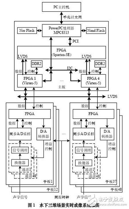
2.2 System ArchitectureThe overall structure of the underwater 3D scene real-time imaging system is shown in Figure 1. It consists of 48 daughter boards, main board and main control PC. The daughter board is responsible for completing the signal acquisition function. The main board is responsible for beamforming and data summarization, and realizes sampling control of the sub-board and communication with the main control PC, and finally completes real-time three-dimensional imaging on the main control PC. Among them, each sub-board has 48 signal receiving channels.

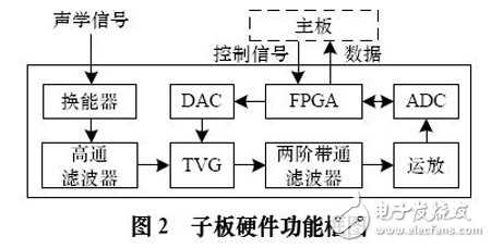
The daughter board is mainly composed of output amplifier ADA4841, 4-channel power amplifier SSM2164, 12-bit serial AD converter ADS7886 and DA converter LTC2641, LTC1019, Xilinx Spartan-3E series FPGA XC3S1200E and other peripheral circuits.
The daughter board data acquisition function is shown in Figure 2. Each channel first conditioned the weak electrical signal received from the transducer, filtered the signal through a high-pass filter to remove the low-frequency ambient noise, and then passed a second-order bandpass filter to achieve the input signal frequency. Greater than 570 kHz attenuates the signal by more than 20 dB while ensuring an effective signal range of 270 kHz to 330 kHz (taking into account the Doppler shift of the hydroacoustic signal) attenuation of less than 3 dB. Then, driven by an external homologous clock, the Spartan-3E controls the A/D sampling chip to perform synchronous A/D sampling and sampling data processing on the amplitude and phase information of the acoustic signal, and passes Low-voltage Differential Signaling (LVDS). The interface uploads data to the motherboard. At the same time, Spartan-3E sends data to the D/A converter through the Serial Peripheral Interface (SPI), and converts the Time Variation of Gain (TVG) control signal to control the sampling signal compression ratio. .

The motherboard consists of one PowerPC embedded processor MPC8313, one Xilinx Spartan-3E series FPGA XC3S1200E and four high-performance Xilinx Virtex-5 series FPGA XC5VSX95T, and other peripheral circuits.
Each Virtex-5 receives data uploaded by 12 daughter boards through the LVDS interface and interacts with each other through high-speed differential pair data lines. Each Virtex-5 calculates the data and completes beamforming. After two 64 MB external DDR2 buffers, the beamforming results are uploaded to Spartan-3E for data aggregation. The MPC8313 reads the data in the Spartan-3E through the Peripheral Component Interconnect (PCI) interface, and transmits the beamforming summary result to the PC host through the Gigabit Ethernet port. At the same time, the MPC8313 uses the system's two-wire serial (Inter-integrated Circuit) (I2C) bus to configure the Virtex-5 registers to generate D/A drive signals to be sent to the daughter board. The MPC8313 peripheral extension has Nor Flash for storing system code, and Nand Flash is used to store system-related data such as the number of valid sensors and the corresponding weight coefficients.
Data Acquisition Analog To Digital Converters
Shenzhen Kaixuanye Technology Co., Ltd. , https://www.iconline-kxy.com
