Design of wireless network communication protocol for smart home
Abstract: Based on ARM microcontroller technology, an effective method of remote monitoring system for smart home is proposed. In practical applications, this method uses a Web browser as the operation interface to realize remote data communication monitoring operations. The nRF24L01 radio frequency module is used to build a wireless data communication platform for smart home terminal devices. The nRF24L01 radio frequency module has a data payload length of 32 bytes. Through the definition of the payload data frame format, the design of the wireless communication protocol is completed, and the application program interface of the underlying device is unified, which adds flexibility to the development of smart homes. The remote monitoring platform effectively monitors the home environment and various control systems, enriching and expanding the operability of home intelligence.
"Smart home" (smart home), also known as smart house, uses advanced computer technology, embedded system technology, network communication technology and sensor technology to organically combine various devices in the home to optimize the user's lifestyle and facilitate The user manages the devices, and can link multiple devices through scene setting.
In the hierarchical structure of the home network, the entire system is divided into 5 layers:
Physical media layer (Media), underlying protocol layer (Protocol), application program interface layer (API), application program layer (APP) and end user interface layer (UI). Among them, the first and second layer standards have been promulgated and applied in practice; the third layer (API) is the key to the development of home network technology and is the focus of current industry research; the fourth layer is the application layer, which is at the third layer Based on various applications developed by technical staff; the fifth layer is various user interface (UI) tools, including various remote control devices, emergency switches, help buttons, and other visual interface devices, to exert the performance of the entire system and Use is essential. This article mainly aims at the third and fourth layer structure, and designs the data communication protocol conforming to the smart home system platform.
1 Overall system plan
1.1 Overall design
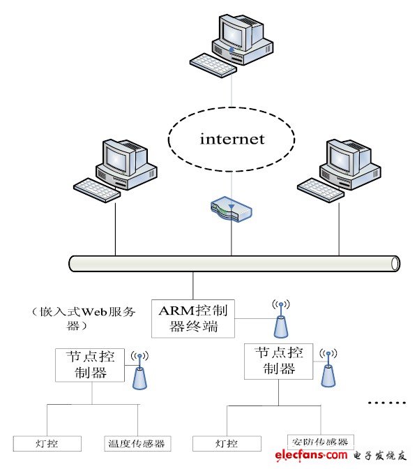
In Figure 1, the ARM main controller acts as a remote Web server for smart homes. It receives remote control data packets through the Ethernet chip ENC28J60. After data analysis is complete, it sends control commands through the radio frequency module, delays and receives the node response data, and the response data is json data. The format (a data saving format) sends partial updated Web information through the gateway to achieve the effect of monitoring and controlling the home environment.

Figure 1 Smart home remote monitoring solution
1.2 Control unit
The control unit uses ARM microcontroller STM32F103RBT6, Cortex-M3 core, 64-pin LQFP package. It has 128K bytes of program storage space, 20K bytes of RAM, and a maximum operating clock of 72MHz. It has rich on-chip resources and has a 7-channel DMA controller. It can support peripherals such as SPI and USART. Suitable for the development and design of low-cost, low-power embedded systems.
In Figure 2, the chip is connected to a total of 3 peripherals through the SPI serial port: SD card interface, Ethernet chip ENC28J60 and RF module chip nRF24l01. The PA4-PA7 port of the ARM microcontroller is used as the chip select signal of the SD card, and the clock signal is led Pins, MISO and MOSI ports; PB12-PB15 are used as chip select signals, clock signal pins, MISO and MOSI ports of the Ethernet chip ENC28J60 respectively; PC6 is the RX / TX mode enable terminal of the RF module, and PC7 is the SPI enable pin , PC10-PC12 respectively as the MOSI, MISO and clock signal pins of the RF module nRF24L01, combined with the micro-control application capabilities of MCS-51 single-chip microcomputer, designed a simple and practical embedded intelligent home gateway and terminal control program.

Figure 2 System control unit design.
With Sdec Engine Diesel Generator
With Sdec Engine Diesel Generator,Sdec Diesel Generator,Sdec Diesel Generator Set,Sdec Power Generator
Shanghai Kosta Electric Co., Ltd. , https://www.generatorkosta.com
