Servo controllers provide performance advantages for medical imaging systems
In recent years, the rapid development of medical imaging technology, the speed of the images produced by the imaging system and the resolution of the images have been correspondingly improved. Due to advances in medical imaging technology, the time required to complete the scan and the limiting factor in the quality of the resulting image are no longer imaging but motion control systems. As a result, original equipment manufacturers (OEMs) of medical imaging equipment began to look for alternatives to the traditional AC induction motors used to position the gantry.
Servo motors are positioned more quickly and accurately than induction motors. However, due to the high inertial load generated by the medical gantry, it was difficult for the servo motor to work under such applications. But more recently, a new generation of drive technology using digital biquad filters has enabled servo motors to be successfully applied to a gantry with inertial loads up to 1000:1, while solving related resonance problems. As a result, motion is more precise, acceleration and deceleration are faster, resulting in higher productivity and sharper images.
Induction motor and servo motor
Open-loop and closed-loop AC induction motors have dominated the imaging equipment scanner positioning market. These imaging devices include computed tomography (CT) devices, electron emission tomography-computed tomography (PET-CT) devices, and X-ray machines. The high inertia of the AC induction motor reduces the mismatch between the motor and the load. However, because medical device manufacturers want to increase the equipment's productivity and image quality, they are often limited by the inherent performance limitations of such motors.
In many applications where fast and precise positioning is required, induction motors have been replaced by permanent magnet servo motors, which can provide extremely high peak torque and continuous torque, resulting in higher acceleration and deceleration rates, significantly improved Precision positioning system performance. The main advantage of this type of motor is that the torque is proportional to the input current, while the speed is related to the input voltage.
The low inertia structure is an inherent design of many permanent magnet servo motors. Therefore, there is a need to consider a large mismatch between the high inertial load of the gantry and the low load of the servomotor. The servo motor control system can be set to meet the inertia mismatch condition, but once the setting is completed, the servo motor response performance decreases due to the increase or decrease of the inertial load. For most medical applications, the load seldom changes; however, belt drives commonly used in these devices cause compatibility or idling problems between the motor and the load, which in turn changes the reflex inertia.
Optimized control system
In order to make the servo system operate effectively, servo amplifiers need to be set to optimize the response performance of the system. Increasing the responsiveness of the system usually requires increased gains. However, too much gain will cause instability and sometimes it will not control vibration. Therefore, the goal of system tuning is to achieve maximum responsiveness while minimizing instability. In terms of motor tuning commands, instability can lead to overshoot.
For example, increasing the inertia value of the control system may cause the motor to execute instructions excessively. On the one hand, as inertia increases, the frequency of instability decreases and longer correction times are required. On the other hand, as the inertia increases relative to a given setting value, the motor becomes unstable and the instability frequency is relatively high. In order to eliminate these vibrations, the system must be demodulated. When the setting value is reduced, the vibration will stop but it will also degrade the system performance.
When the gain is -3dB or less, the output phase changes by -45 degrees or less from the control signal, or -135 degrees from the motor reference value, the control system loses control. As is well known, the open-loop transfer function uses two methods to predict stability problems: phase margin (PM) and gain margin (GM). The phase margin is the difference between the open-loop phase corresponding to the frequency at which the gain is 0 and -180 degrees. The gain margin is the negative value of the open-loop gain corresponding to the frequency when the phase passes through -180 degrees. The greater the unpredictability of the load, the greater the phase margin and gain margin, to ensure the stability of the control system.
For example, when the resonant frequency is much lower than the initial phase crossover frequency (270 Hz), the effect of the compatible load is to reduce the gain margin. If the inertia mismatch value is 5, the gain margin is reduced by 6, which is approximately 16 dB. Assuming no other correction method, the gain of a compatible coupling system has to be reduced by 16 dB compared to a rigid system, provided that both systems maintain the same gain margin. A large reduction in gain will worsen the system's ability to receive instructions and interfere with response.
Filters enable servo controllers to manage compatibility
Recently, manufacturers of servo control systems have significantly increased the ability to compensate for inertia mismatch and compatible loads. The basis of these studies is that compatible mechanical systems usually have some resonance points that are easy to oscillate, while at the same time they will achieve better performance at other frequencies. The traditional way is to use low-pass, bandpass and high-pass filters to eliminate harmful frequencies. The problem with the method itself is that the elimination of all resonances by a plurality of filters leads to computational delays and phase shifts, which can easily cause the system to lose control.
Recently, the use of biquad filters has significantly improved the performance of the system. The biquad filter consists of two quadratic equations with five coefficients so that the filter can simulate almost any combination of simple filters without causing significant delays. By setting the frequency of the problem, the biquad filter achieves the goal of improving the phase margin and gain margin to optimize the performance of the servo system. For example, the mechanical system has a resonant frequency of 200 Hz and can be configured with a biquad filter to eliminate 200 Hz while maintaining high gain at lower control frequency points.
It should be noted that the large belt-driven gantry has a strong physical roll-off, so that they cut off all frequencies higher than about 10 Hz like the low-pass filter. By truncating the gain at the 10 Hz point while passing the speed loop between 30 Hz and 40 Hz, the gain at the critical control frequency point (approximately 2 to 4 Hz) can be significantly increased.
Velocity feedback devices combined with dual-quadratic filters can significantly improve the performance of systems that face low-frequency resonance problems. Compared with the traditional single-pole low-pass filter, the biquad filter and gain combination can reduce the correction time by one-third and increase the bandwidth by one-third. At the same time, the feedback device maintains stability margins by significantly reducing acceleration and jerk forces.
Therefore, a new generation of servo controllers can be configured to provide the gain margin and phase margin needed to compensate for high inertial loads and compatibility in image applications. Manufacturers of medical imaging equipment can and hope to take advantage of the higher accelerations and speeds provided by servo motors in order to significantly increase the customer's productivity. In addition, major manufacturers of servo systems have increased manufacturing efficiency and reduced the cost of servo technology to the same level as AC induction motors.
image
figure 1
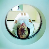
Explanation: Advances in servo technology have made servo systems faster and more accurate than inductive drive systems. Medical imaging original equipment manufacturers (OEMs) can provide devices that scan faster and produce higher image quality.
figure 2
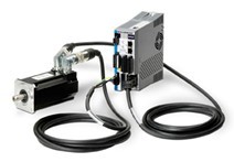
Explanation: Servo systems with dual-quadratic filters have significant advantages in scanning frame applications. This kind of servo system can provide more accurate transmission and faster acceleration and deceleration, so compared with the induction drive, the production capacity is improved, and the resulting image is also clearer.
Figure 3 - Figure 4 - Figure 5
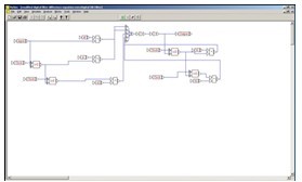
Biquad filter block diagram
Note: The biquad filter maximizes the performance of the servo system in scanner applications. Using different coefficients, the biquadratic filter implements notch filters, low-pass filters, and resonator filters through a single filtering technique.
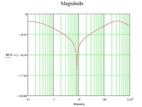
Explanation: By generating a nodal function at a specific frequency of 900 Hz, the frequency of 900 Hz can be significantly reduced. The figure shows the 900 Hz input frequency entering the filter. Due to the notch filter, the output amplitude of the filter is significantly reduced.
Note: Now the frequency of entering the filter has been reduced, and the frequency interference outside the 900 Hz point is very small. You can adjust the width, cutoff depth, and overall shape by lowering the gain. In addition, the variance does not require more filter cascades - only different coefficients are needed. The biquad filter can also be automatically adapted to avoid any high-frequency resonance that may interfere with the system.
Figure 6 - Figure 7 - Figure 8
Explanation: This figure illustrates the system transfer function for handling large loads. The system reaches a peak at about 135 Hz, and trying to increase the gain at this frequency will result in system instability and resonance. However, using a simple biquad filter can provide superior gain margin by increasing the lower frequency while truncating the higher frequencies. Therefore, the digital filter system can increase the frequency range of 10 Hz and reduce the frequency range of 135 Hz.
Explanation: This figure explains the shape of the transfer function when using a biquad filter.
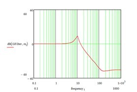
Note: When the biquad filter is integrated into the transfer function of the resonant system, the high frequency is truncated and a flat response with higher gain is obtained. In this example, the resonance peak is reduced by 40 dB, which is equivalent to 100 gain. In this way, the gain can be increased proportionally, resulting in a high frequency response and a more stable system.
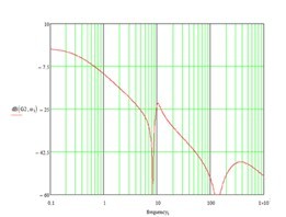
Figure 9 - Figure 10
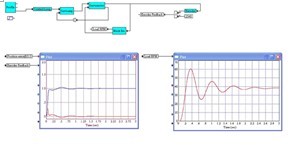
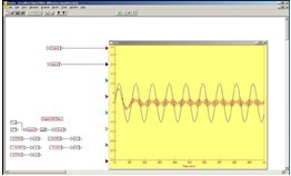
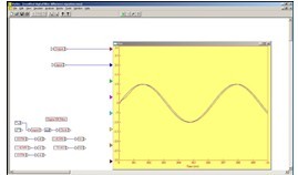
Explanation: The VisSim (visual solution) model of a compatible mechanical system is used to analyze the operation of the controller. The figure on the right shows that the load is vibrating when the controller corrects the position loop. This is what happens when the gantry uses a belt drive with a high inertia mismatch ratio. The amplitude of the movement of the load is significantly greater than the identification range of the control system, and the echo causes vibration.
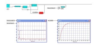
Note: When the inertia ratio of the load motor decreases from 50:1 to 10:1, the stability increases, and the clear position and speed diagram shows no vibration. The acceleration time is reduced, the actual speed trajectory is closer to the command, and the correction time is minimized.
Asterbar Disposable ecig have a completely enclosed design, reducing the need for charging and replacing cartridges. The no-charge design also reduces the occurrence of faults. It is understood that with rechargeable e-cigarettes, each cartridge needs to be charged at least once and the battery efficiency is extremely low, while the design of disposable ecig can solve this problem very well.
Disposable Asterbar E-Cigarette,Mini Asterbar E Cigarette,Asterbar Electronic Cigarette Customizing,RechargeableAsterbar E Cigarette
Shenzhen E-wisdom Network Technology Co., Ltd. , https://www.globale-wisdom.com
