Solomontech's driver chip succeeds in making bistable display a reality
The bistable display technology has become one of the most modern display technologies and has received close attention in the industry. This has become a real matter when end products begin to be produced on a large scale with a bi-stable display. A cholesteric display is one of the bi-stable displays that has been used in memory drive devices to display the amount of space remaining in the memory. It is used in electronic vending point systems (ePoP), such as display products for price tags. Another type of bi-stable display, the electrophoretic display, has been applied to different styles of Sony e-books in SVGA display sizes. In addition, Motofone, a new Motorola mobile phone, uses an electrophoretic display as its main display and has millions of products. These applications show that bistable display technology is no longer a fantasy technology, but rather it has become a display technology that has passed the test of the mass production requirements of portable devices.
This article refers to the address: http://
A number of bistable display technologies have emerged. Among them, after decades of development and evolution, electrophoretic and cholesteric liquid crystal displays have been realized in large-scale production of terminal products with their superiority. Now let's take a look at these two technologies and try to find out why they can compete with traditional display technologies (liquid crystal displays and organic light-emitting diode displays) and account for a certain market share as a display device solution.

Figure 1 Motorola's world's first electronic paper phone Motofone, using Solomon's bistable display driver chip
Electrophoretic display
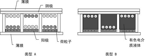
An electrophoretic display consists essentially of a plurality of small chambers between films, each containing a dielectric fluid and charged pigmented particles. A common transparent cathode (Cathode) is placed on top, and a separate anode (Anode) is placed at the bottom of each chamber. When an anode positive and negative electrical signal is supplied from the driver chip, electrophoresis occurs and charged particles are attracted to the top or bottom of the chamber as shown in FIG.

Figure 2 Electrophoretic display structure
The display has two different principles for displaying two colors. For type A, there are two kinds of charged particles, one is white and the Other is light absorbing. When the white particles emit white light at the top, the display is lit; when the black particles are at the top to absorb light, the display is not displayed. Type B contains white particles and colored liquid in the chamber. The principle of lighting state is similar to A. However, when the white particles move to the bottom, the display will be converted to another color, which can be seen by the user. The color of the dielectric liquid.
Cholesteric liquid crystal display
The cholesteric liquid crystal display (ChLCD) has two stable states: a plane and a focal conic. In the planar state, the surrounding light enters the ChLCD and is split into two polarized lights, one beam passing directly through the display and the other beam being reflected back in the form of scattered light, thereby causing the pixel to illuminate; when there is a focus state, enter The light passes directly through the display without reflection and the pixels do not illuminate. The driver chip provides an electrical pulse to the cholesteric liquid crystal display, allowing it to switch between these two states.
Bistable display features
A bi-stable display displays an image by scattering light from particles, dielectric liquid, or ChLCD. It does not require a polarizer commonly used in LCDs (the polarizer absorbs most of the light). The bistable display has better reflectivity and achieves high brightness and high contrast. In addition, the scattering of light also gives the image a wide range of viewing angles. Therefore, the bi-stable display can provide high readability comparable to paper quality.
The bistable display is a non-emissive technique by displaying images using scattering from ambient light. It consumes less energy than an emissive display such as an OLED because the latter requires a lot of power to produce brighter light than the external environment to display images with better readability. Moreover, electrophoretic displays also exhibit bistability: power is only required when the image is changed, and the image can remain displayed without power. Traditional displays such as LCDs and OLEDs must constantly use power to update the display in order to maintain the image. The bistable display is significantly more power efficient than conventional display technology.
As we have seen, the structure of an electrophoretic display is very simple and consists of only a few layers of material, without the polarizers, backlights and diffusers required by the LCD. Therefore, it can be made thinner and can be less than 0.2 mm thick. The film layer of the electrophoretic display is made of plastic, and the bottom plate is a flexible printed circuit board, so that the electrophoretic display can be bent; while current LCD and OLED displays require rigid glass.
Due to the unique characteristics of the bi-stable display, thin and flexible, it can open up some end products market where traditional displays cannot be deployed. For example, electrophoretic displays are applied to smart cards and memory cards. In these applications, they require thinness and thickness to meet standards, while thick LCD/OLED glass cannot be achieved. In addition, smart card requirements can be bent to a certain extent, which is unlikely to be achieved for LCDs and OLEDs. It is foreseeable that bi-stable displays will be more widely used in fields where conventional displays cannot be used due to size and mechanical performance limitations.
Other advantages, such as good display readability, high contrast, wide viewing angle and ultra-low power consumption, make bi-stable displays very competitive in portable products such as cell phones, clocks, electronic shelf labels, and e-books. The advantages of the bi-stable display are the main factors that these products need to consider when selecting a display solution.

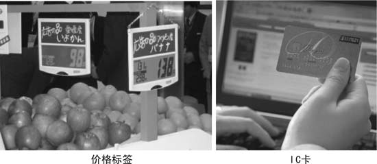
Figure 3 Electrophoretic display application example
This promising dual display technology also has its drawbacks: the display requires a high drive voltage of approximately 30 to 40 volts in order to convert material from one stable state to another. This high voltage is usually not available in portable device systems. Different types of bistable display technologies contain different drive waveforms. In addition, the waveform is usually too complicated, and it would be very laborious to use an ordinary microcontroller to output the appropriate waveform to control the display. For some bi-stable displays, their optimal display drive parameters will change with temperature. Nonetheless, Solomon Systech's bistable drivers are flexible enough to handle these situations, allowing more products to use bistable display technology.
Driver chip
Currently, Solomon Systech has two highly integrated driver chips designed for bistable displays: the SSD1615 and the SSD1621.
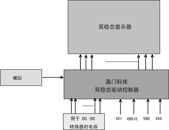
The SSD1615 is a driver chip with a controller for passive matrix type cholesteric liquid crystal displays that supports up to 132 segments x 64 shared channels. The SSD1621 is also a driver chip with a controller, but is used to control the direct drive segment or image of an electrophoretic display. It has 93 segments and a shared channel with three voltage levels as outputs. A single 2.4~3.5V low voltage source input is sufficient for the entire display operation of the chip. The chip's internal DC-DC converter converts the input low voltage to voltages up to 30V (SSD1621) and 35V (SSD1615) to drive the bi-stable display. They also contain built-in drive waveforms for bistable display. Users do not need to deal with complex waveforms, just send the display content to the internal display buffer, the driver chip will automatically output the appropriate waveform to change the display content. The SSD1615 also comes with an internal temperature sensor. Based on the ambient temperature, the driver chip adjusts the drive waveform parameters accordingly to ensure that the display is in optimal display. Both driver chips support common MCU interface and image data access: the SSD1621 supports the SPI interface, while the SSD1615 supports the SPI, I2C, and 8-bit parallel interface buses in the 8080/6800 mode. The application circuit of the two driver chips is very simple, as shown in Figure 4. Only a small external capacitor is required to operate the internal DC-DC converter and stabilize the voltage. This simplifies the circuit design and minimizes the circuit area, making the entire system simpler.

Figure 4 Spiegel Technology bistable driver chip application circuit diagram
Conclusion
The bistable display has become a reality and has been applied in the market. The attitude within the industry has shifted from skepticism to adoption of this technology, which has been proven in an exciting number of end products of millions of units. Solomon Systech is committed to the bistable display industry and has developed a series of driver chips to achieve the best display for bistable displays.
Motorola Mobile Radio,Motorola Walkie Talkie Phone,Motorola Vhf Mobile Radio,Motorola P25 Mobile Radio
Guangzhou Etmy Technology Co., Ltd. , https://www.gzdigitaltalkie.com
