Electromagnetic induction wireless charging core technology (1): resonance control
In this paper, we will explore the three core technologies currently in electromagnetic induction wireless charging systems: resonance control, high-efficiency power transmission and data transmission, as well as their problems and existing solutions.
Resonance control
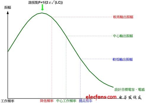
Today's mass-produced IC processes have progressed to the nano-level, but the specifications for mass-produced capacitors and inductor components are difficult to make the error below one percent, while in the electromagnetic induction power system, two coils are used to induce The coil is the inductor, and the capacitor needs to be matched with the capacitor as the resonance matching. Such a structure is the same as the LC oscillating device. The difference is that the purpose in this system is to transmit power on the coil. In order to improve the efficiency, the capacitor is needed. The inductor uses low-impedance parts to improve the quality factor Q. Under such a design, the slope of the resonance curve becomes very large. In the mass production, the system design frequency is very difficult to match with the capacitor and the inductor, because the capacitor is mentioned before. There is a considerable error in the inductance. If the error in mass production is not added to the resonance control correction error factor in the system, the yield of the finished product is difficult to control. In the case of capacitance and inductance errors, the combination of the original design resonance points will be matched, resulting in a deviation of the transmission power from the predetermined design value. Referring to Figure (1), the amplitude of the signal on the coil of the transmitting end in the electromagnetic induction power system is the magnitude of the output power. In this diagram, the resonance curve of a combination of coil and capacitor is shown; The frequency of operation has different amplitude amplitude outputs on the coil at different operating frequencies, and the resonant power of the maximum amplitude will appear above the frequency F=1/(2π√(LC)), which is not designed. Setting the system at the resonance point of the highest power output will work at a higher frequency than the resonance point to maintain the output power at an appropriate value. In the system, we usually call this frequency the center operating frequency. In the inductive power supply process, it may be necessary to increase or decrease the output power. In this case, the operating frequency can be adjusted. As shown in Figure (1), when you need to add power, you need to lower the frequency to bring it closer to the resonance point to increase the output power. Otherwise, you can reduce the output power by increasing the frequency. This method is defined as frequency conversion. Power adjustment.

Figure (a) frequency conversion power adjustment
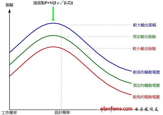
Another way to change the output power is to change the driving voltage on the transmitting end. As shown in Figure (2), in the resonant combination of the same coil and capacitor, the switching voltage on the transmitting coil is the directly changed output power. The size of this is defined here as a transformer power adjustment.

Figure (2) Transformer power adjustment
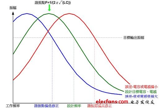
It has previously been mentioned that the errors in coils and capacitors in mass production need to be corrected. The purpose of the correction is that each group of products needs to have a consistent power output setting. Referring to Figure (3), this is the resonance curve of a typical mass production product. There are products with high and high resonance points. In the variable frequency system, in order to start charging and charging power, it is expected to be set. In the combination of high resonance point (small capacitance or inductance value), the center operating frequency is increased to make the output power the same as the design target. On the contrary, when the resonance point is low, the reverse operation is performed. As shown in (3), the frequency conversion system Have ample correction tolerance.

Figure (3) Frequency conversion resonance deviation correction
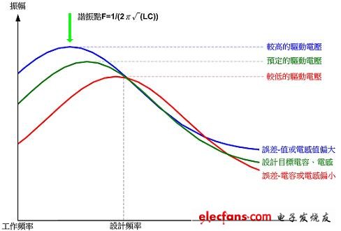
Another way to correct the resonance deviation is the transformer type. The method of changing the driving voltage is shown in the figure (4). When the resonance point is high (the capacitance or inductance value is too small), the driving voltage is lowered to reduce the power output to The predetermined value is designed, and vice versa when the resonance point is low. It can be seen that with the adjustment method of the variable voltage type, the correction tolerance space is narrower than that of the frequency conversion type, mainly because the correction range of the voltage change does not change the frequency mode, and the control adjustment range is better because the reaction is slower.

72V 125Ah Power Battery,Portable Solar Power Station,72V Camping Power Battery,Rv Mobile Energy Storage Power Supply
Sichuan Liwang New Energy Technology Co. , https://www.myliwang.com
